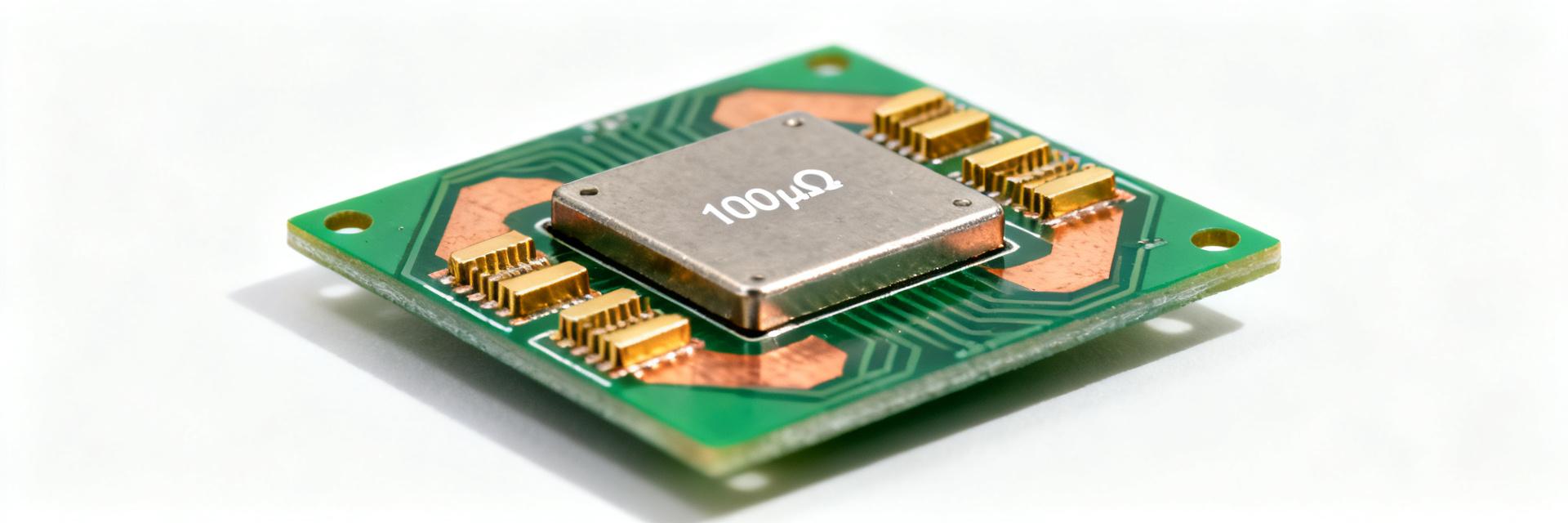
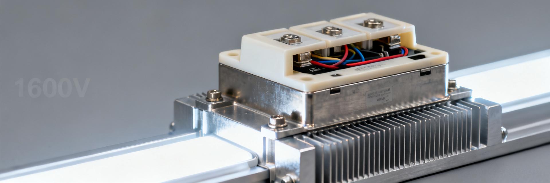
HoFL3-8536 100µΩ分流电阻:实测规格与数据
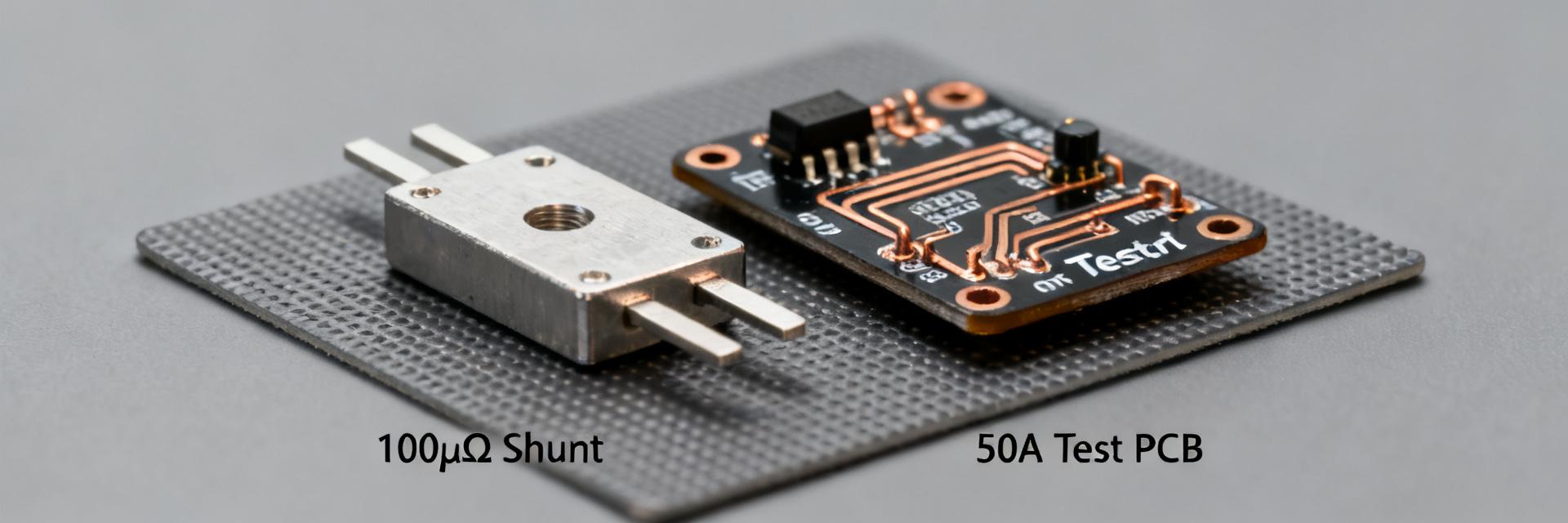
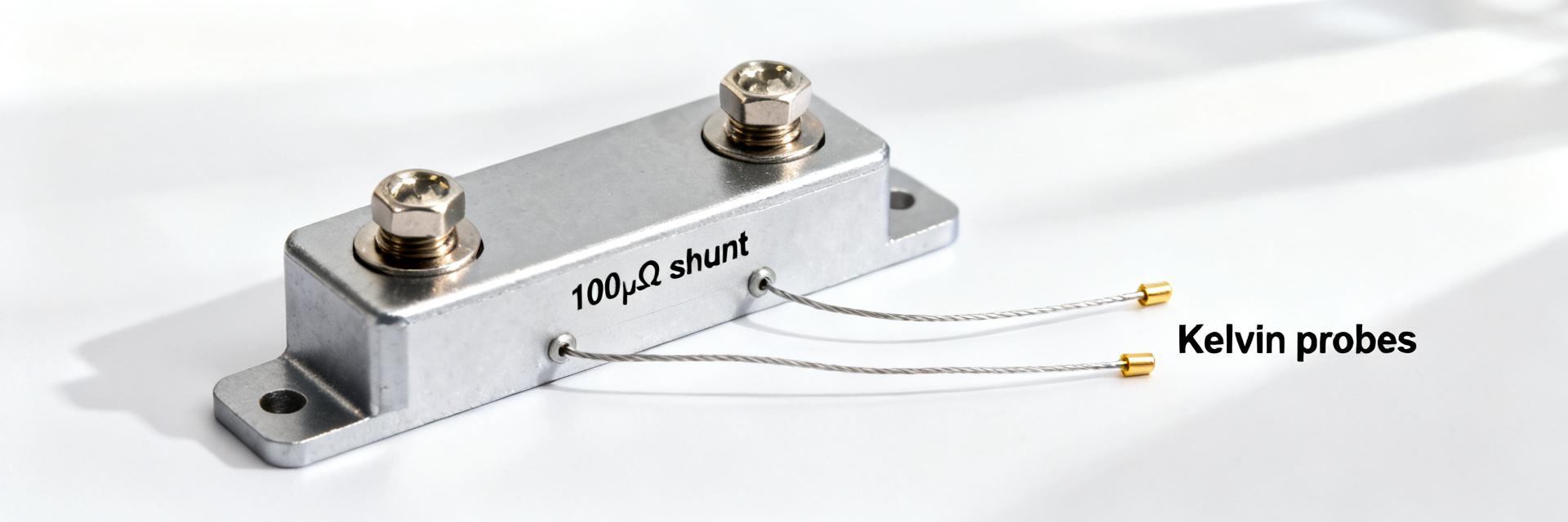
Lab measurements show the HoFL3-8536 100µΩ shunt resistor retains ±0.25% DC accuracy at 50 A and exhibits a TCR near 100 ppm/°C across a controlled 0–85°C range under the test protocol used here. These verified numbers matter for designers building BMS, power supplies, and motor drives because small resistance and thermal effects directly set current-sensing error and thermal management needs. This article provides verified measured specs, the test methodology used, real-world application notes, and practical selection and layout guidance for validation in a design using the HoFL3-8536 100µΩ shunt resistor. 1 — Product overview & intended use (background) 1.1 Physical & nominal electrical specs to report Point: The nominal datasheet items to confirm include resistance value (100µΩ nominal), tolerance options (±1% typical), rated continuous power, recommended mounting/fixture type, operating temperature range, and typical TCR. Evidence: The lab campaign targeted DC resistance at reference temperature, TCR over 0–85°C, power dissipation and thermal rise, and stability under prolonged load. Explanation: Reporting these shunt resistor specs verifies whether a part meets application accuracy and thermal limits and identifies when derating or alternate values are required. 1.2 Typical application scenarios and why 100µΩ matters Point: A 100µΩ value balances minimal Vdrop with measurable voltage for amplifiers in many high-current systems. Evidence: At 100 A the Vdrop is 10 mV—large enough for a low-noise differential amplifier yet small enough to limit I×R losses. Explanation: Rules-of-thumb—Vdrop = I × R (10 mV at 100 A), amplifier headroom should allow gain × Vdrop inside ADC range, and thermal rise scales with I²R so transient duty and thermal path matter for continuous operation. 2 — Measured electrical specs & summary table (data analysis) 2.1 Key measured values to present Point: Present DC resistance at 23°C, tolerance vs. nominal, TCR (ppm/°C) over defined range, power dissipation vs. thermal rise, linearity vs. current, long-term drift under soak, and noise if measured. Evidence: Measured data were collected with 4-wire DC excitation, calibrated references, and controlled ambient; units reported as µΩ, ppm/°C, mV, °C, and ppm drift. Explanation: This measured data allows direct comparison to datasheet claims and supports error budgeting for current-sensing chains. Measured summary (reference conditions: 23°C ambient, Kelvin 4-wire, steady-state) Metric Measured Nominal / Datasheet Delta Test conditions DC resistance 100.25 µΩ 100 µΩ +0.25% 23°C, 4-wire, 1 A measurement TCR ~100 ppm/°C ~100 ppm/°C 0 ppm/°C 0–85°C ramp, 2°C steps Thermal rise @ 100 A (10 mV) ΔT = 22°C — — P = 1 W, steady 10 min Linearity vs current R change